
Thomas 4L/G8BAG
The vertical antenna described here will never replace a good horizontal beam antenna for ten, but if space and materials are limited, the antenna works extremely well for a very low cost and simplicity of construction.
I live in a village where we have only one hardware store with NO materials whatever, which are even suitable for any antenna construction. Not being one to give in to such adversity, I decided to make the best of anything I could find. I settled on a 10m vertical antenna 1/2 wave design using whatever I could lay hands on.
After a bit of thought and browsing the hardware store shelves, I came up with a plan to make a “flower pot” half-wave vertical antenna, at least to get me on the air until I built my Moxon antenna.
The Moxon antenna, a novel design using more off-the-shelf building materials, is the subject of another post.
The hardware store did not sell “sky hooks” so I had to find a way to suspend the antenna as a standard flower pot is simple a length of coax, choked at the correct length and fed to the transceiver.
Most flower pots tend to use fishing poles or some-such means of keeping the beast vertical. I decided that the hardware store’s 60mm (2+ inch) plastic drain pipes were a good idea. They would give some strength to a vertical antenna and through their solidity, would allow the fitting of guy ropes against wind.
So how did I make it?
I bought 2 pieces of 60mm (2 inch) plastic pipe at 3 m (10 feet) each
2 nylon washing lines and 50 ft or what ever suits you, of 75 Ohm coax ( why 75 Ohm? ) Simply because they never heard of 50 Ohm and 75 was in stock for satellite dishes. If everything else was right, 75 Ohm would still give me an SWR of 1.5:1 which is no problem at all (SWR has nothing to do with impedance matching and the MFJ 258 took care of this).
I laid out the coax and measured 2510 mm (98.8 inches) from one end. At this point, cut off the outer sleeve and the braided sheath leaving only the inner wire still in its plastic covering. Measure a further 2450 mm from this point and mark the cable with a marker pen.
With the two sections of pipe coupled together ( they push-fit into each other ) measure a little over 5 meters (100 inches) from one end and drill a hole 6.5mm (1/4″) in diameter into the pipe at this point. The length I mentioned is unimportant as long as it’s a little over 5 meters (200 inches).
When drilling that hole, finish by angling the drill toward the longest end of the pipe whilst not enlarging the hole. Now push the coax, stripped end first, into the hole so that it goes toward the longest part of the pipe. It will go quite well as coax is not flexible enough to bunch up inside.
Keep going until the bared end of the coax emerges from the pipe. This will be past the mark which you put on, but there’s a reason.
Now remove about 50 mm (2 inches) from the inner insulation at the end of the cable which has popped out of the top of the pipe. Bend this over and twist it into a loop so that the final 5cm (2 inches) is used up, effectively reducing the length by 5 cm. Securely attach 30mm or so (about a foot) of nylon cord to this loop and tie something to it which can not enter the pipe.
Go back to where the cable emerges from the hole you drilled and gently pull on the coax until the mark you made on the coax just appears. STOP.
Go back to the nylon cord which is out of the end of the pipe and gently pull it until the cable inside the pipe is fairly straight.
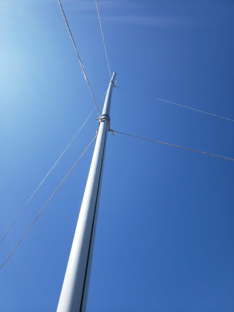
You are now going to cap this off so that when the antenna is vertical, the cable inside the pipe hangs from the nylon cord. There are blanking caps available for this pipe but I couldn’t find any in my hardware store, so I stole one of my wife’s empty face cream plastic pots, which fitted tightly over the end of the pipe trapping the nylon cable in position. The cap has now been replaced with the correct plastic type.

The metal cap in the photo was replaced by a plastic face cream jar.
Important: Just below where you cap it off, drill a small hole in the pipe. A 3mm drill will do fine. This avoids any condensation building up in the pipe and is too small to allow rain to get in.
Back to the point where the cable comes out of the hole you drilled earlier.
At this point, the cable within the pipe has a high impedance at 10m, so we need to bring that down to low impedance.
With the remainder of the cable now lying outside the pipe, closely wide 10 turns around the pipe, starting directly at the hole. This will choke off the high impedance of the antenna. Now drill two more holes. The first should be directly at the point where the 10 turns finish. The second hole should be near the end of the pipe below the coil of cable you just wound.
The photo below shows 24 turns which I had interpreted incorrectly originally. The coil is now 10 turns, but the photo is included as the black tape covers the connection of the antenna proper inside the pipe to the coil. I made this connection so that the choke could be tuned without the antenna connected.
Push the coax into the hole beneath the coil (which is now an RF choke) and retrieve it from the end of the pipe. Now it’s inside the pipe.
Short the inner of the top end of the coil to the inner and check the self-resonance of the coil with an antenna analyser at the radio end of the coax. If the resonance is less than 28 MHz remove a turn and retest. The aim is for a self resonance of around 30 to 33 MHz. The self-resonance should be found at around 9 turns.
The second hole you just made is for the cable to come out without the pipe standing on it when in the vertical position.

From the inside, push the coax through so that it comes out on the outside of the pipe.
Tune the antenna to the correct frequency – mine was first tuned to 28.5 then extended slightly to tune at 28.4 MHz as slightly long will give the best radiation for DX at 28.5 MHz. In the end I decided that this was unimportant as transmissions were never going to be at a fixed frequency of 28.5 MHz.
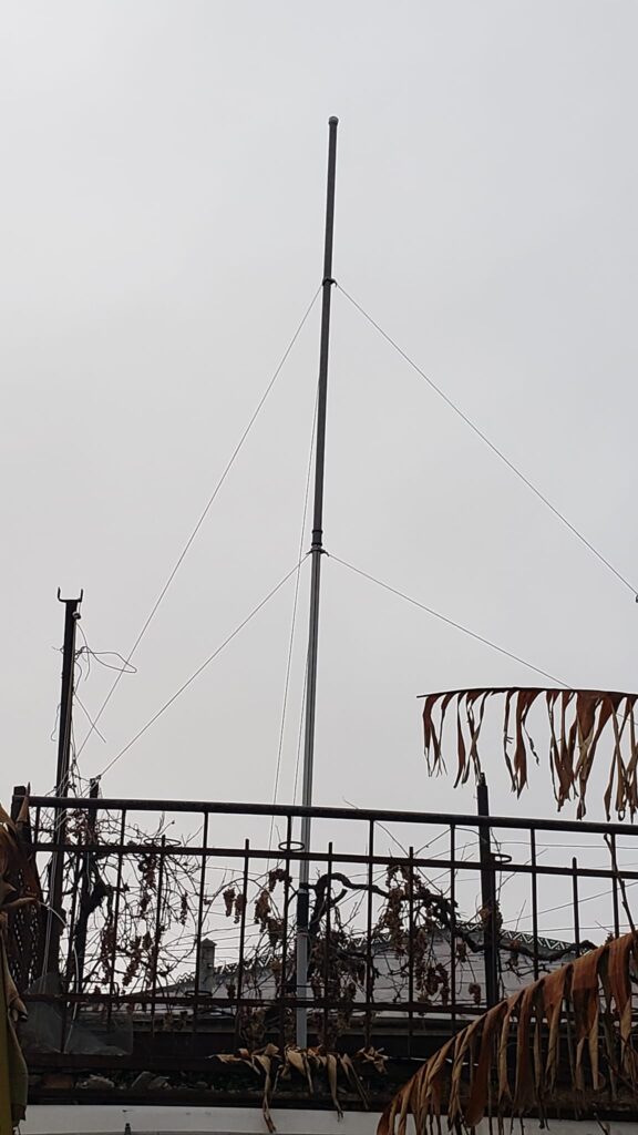
Sticking it up in the air.
The antenna is finished, but you still need to check it and get it up in the air.
I had a couple of near disasters here, so lessons learned follow.
The antenna needs at least 3 sets of guys. My first point is 1.5 metres ( 60 inches) from the top. The second, just below the joint of the two pipes and the third, just below the choke coil. I had missed this third one originally and the antenna collapsed in a high wind at that point, which brought the whole thing down, breaking the sleeve which was meant to accept the pipe above it. A one meter length of pipe is ideal as the bottom section.
Assuming:
- roof height ≈ 3–4 m
- radiator ≈ 5 m long
Then current maximum occurs roughly:
- 1.2–1.5 m above roof
This one meter section of pipe is good for DX.
Several high winds after I added this point, have not been able to move the antenna at all.
How to anchor the cable to the pipe.
I bought three of the plastic clamps which hold the pipe to a wall when used in their original use for drainage. I glued and screwed these to the pipe at the points I mentioned …CAUTION.. USE SHORT SCREWS so that you don’t pierce the cable within the pipe or your antenna is already dead.

With these clamps glued and screwed in place, I found that the plastic mouldings had ribs which were easily drilled to take my guy ropes. I used three ropes at each point. Three or even four is fine.
Lie the antenna in the most vertical position you can for testing purposes. It’s not so critical for tuning. I had no changes to make to mine which showed 1.3:1 on the antenna analyser when leaning against the kitchen roof.
The assistance of a second person is useful here. Raise the pipe vertically and hold it upright whilst you or your assistant finds, or knocks in anchor points for the guys. The guys are cut from the cheap nylon washing lines. Check, check and check that the pipe is as near vertical as possible and that no guy rope is trying to pull it out of shape. After it has stood for a few weeks, recheck guy rope tensions. After strong winds, my antenna guys had slackened slightly and since then, nothing has moved, despite what the weather has thrown at it.
Your antenna is ready for testing.
I used my antenna analyser for this and was lucky enough to find that regardless of any fine tuning or the fact that I was using 75 Ohm cable into a 50 Ohm transceiver, my SWR was 1.6:1 and the MFJ 258 ATU soon put the matching to rights.
At first, I thought I had a fault. No power output from the radio according to the built-in SWR meter. Then I found that the SWR was so good, that I was on reflected power setting instead of forward, which showed full power with nothing coming back.
This antenna has proved itself over spring, summer and winter. The SWR remains at 1.1:1 and from Georgia has worked, W, VK, BG, G, JA, VR2 and many others on all continents with 100W SSB from a 30-year-old Yaesu transceiver.